
How a Speaker Works
Note: This topic is an excerpt from the on-screen manuals of BassBox Pro
and BassBox Lite. Much more information is available in the manuals.
The word "speaker" is the shortened form of the word "loudspeaker" and it refers to a device that converts electrical signals into sound waves that we can hear. A speaker has several parts:
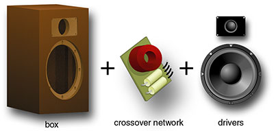
- Box – houses the drivers and, if present, a passive crossover network.
- Crossover network – divides the audio signal between the drivers.
- Driver – converts the electrical audio signals into sound waves.
Sometimes people refer to the drivers as speakers. Yet, the speaker is really the entire system, including box, crossover network (if present) and drivers. Let’s examine each part beginning with the drivers.
![]()
Drivers
There are many different kinds of drivers but they all do basically the same thing: create sound waves. By far the most common type of driver is the moving coil electrodynamic piston driver. It has a moving part called a diaphragm that acts like a piston to pump air and thereby create sound waves. A common diaphragm for a woofer is a paper cone. A common diaphragm for a tweeter is a fabric dome. The moving coil piston driver is the type that our box design software (BassBox Pro and BassBox Lite) and passive crossover design software (X•over Pro) model and so we will focus our discussion on them.
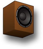
Why do drivers come in so many different sizes? Because it is nearly impossible to make one piston driver that can reproduce sound waves over the entire 20 Hz to 20 kHz frequency range of human hearing. To produce low frequencies a driver needs to have a large diaphragm and enough mass to resonate at a low frequency. To produce high frequencies a driver needs to have a small diaphragm with a low mass. Obviously, these requirements are in opposition so drivers are usually designed to produce only a portion of the sound. This gives rise to multi-way speaker systems like the two-way system shown above. It uses a tweeter for the high frequencies and a woofer for the low frequencies.
Besides their different size, there is another very significant difference between a tweeter and a woofer. The tweeter usually has a sealed back while the woofer usually has an open back. With a sealed back, the tweeter emits sound waves from the front side only. A woofer emits sound waves from both its front and back side. We’ll see later that box design is dominated by the woofer because of this difference.
Tweeters are the smaller drivers since they produce the highest frequencies with the shortest wavelengths. Woofers are the largest drivers since they produce the lowest frequencies with the longest wavelengths. Are there other driver sizes? Yes, there are also midrange drivers of various sizes that reproduce middle frequencies between the tweeter and woofer. Midrange drivers are used in multi-way speakers with three or more driver sizes. Some have open backs and some have sealed backs.
A cutaway view of a typical woofer is shown below:
Next, let’s examine each of these parts. They are organized below according to their function.
Motor parts:
- back plate, center pole, front plate – these three parts are usually made of iron or a similar permeable material to form the magnet circuit with the magnet. The front plate and pole piece form the "gap" of the magnet circuit. All three parts, along with the magnet and frame, serve to dissipate heat away from the voice coil. Some drivers (usually small ones such as tweeters and midrange drivers) include ferrofluid in the gap to further cool the voice coil and provide resonance damping.
- magnet – provides a stationary magnetic field to oppose the alternating electromagnetic field of the voice coil and thereby cause the attached cone to move inward and outward. Most drivers use a ring shaped magnet that is made of a ferrous ceramic material.
- screen, vent – some drivers include a rear vent to prevent pressure from building behind the cone in the magnet assembly and to provide cooling of the voice coil. A screen is usually provided to prevent debris from entering through the vent.
- voice coil & former – the voice coil is a coil of wire, usually copper or aluminum, through which the electrical audio signal flows. The flowing current of the audio signal alternates, creating an electromagnetic field which is opposed by the permanent magnetic field of the magnet circuit. This causes the voice coil and diaphragm to move. Some drivers have two (dual) voice coils to provide various wiring options, including the ability of simultaneously connecting two different signals to the driver. Voice coils can be "overhung" or "underhung" as shown below:
An overhung voice coil is taller than the height of the gap while an underhung voice coil is shorter than the height of the gap. Overhung voice coils are the most common. Underhung voice coils can offer the advantage of a more linear motor strength (BL product) over their excursion range (Xmax) but they are usually more expensive—especially when a large excursion is desired. Finally, the voice coil is wound around the former which serves as a heat-resistant spool for the wire.
- connection terminal – provides a way to make an electrical connection to the voice coil. A variety of terminal types are used, including simple push-on terminals or gold-plated 5-way binding posts. The positive terminal should be labeled "+" or with a red dot. When the driver is wired so that a positive signal flows to the positive terminal, the cone should move outward. If it moves backward, the terminal labels are reversed. Drivers with dual voice coils will have two sets of terminals.
Diaphragm parts:
- cone – also called the "diaphragm", moves like a piston to pump air and create sound waves. The mass of the moving parts (the cone, dust cap, voice coil and former) and the compliance of the suspension (surround and spider) control the resonance (Fs) of the driver which in turn controls its low-frequency response.
- dust cap – covers the hole in the center of the cone. This has several benefits: it reduces the amount of dust and dirt that can get into the gap of the magnet, it reduces the leakage losses (QL) through the driver, it adds strength to the cone while helping to maintain its shape and it can add mass to the cone to help lower the driver’s resonance (Fs). Some dust caps include a screen or vent to allow airflow and aid cooling of the voice coil.
Suspension parts:
- spider, surround – these two parts form the suspension of the driver. The suspension fulfills several purposes: it centers (both axially and front-to-back) the voice coil in the gap of the magnet circuit and it exerts a restoring force to keep it there, it limits the maximum mechanical excursion (Xmech) of the diaphragm and voice coil, it determines the compliance (Cms and Vas) of the driver and together with the mass of the moving parts determines the resonance (Fs) of the driver. Ideally, the suspension should provide a linear restoring force on the diaphragm and voice coil over its full range of excursion.
Frame parts:
- frame – also called the "basket" or "chassis", provides a rigid structure to which the driver components are mounted. It must be made with a high degree of precision so that all of the driver components will align properly. The frame can also aid the motor parts in dissipating heat away from the voice coil. It is commonly made of stamped steel, cast aluminum or plastic.
- gasket, optional gasket – most drivers include a front gasket to provide a smooth and flat mounting surface. However, since most drivers are mounted using the back side of the mounting flange, a rear (optional) gasket is often desired. The driver should have an airtight seal to the box.

Crossover Network
Most speakers must use more than one size driver because it is extremely difficult for one driver to accurately reproduce sound waves over the entire 20 Hz to 20 kHz frequency range of human hearing. The most common multi-way speakers use two drivers, a tweeter and a woofer. This requires the electrical audio signal to be divided into a high-frequency part and a low-frequency part before the signals reach the drivers. This is very important because most tweeters will be damaged if they are driven with a low-frequency signal. The illustration below shows the sound being divided between the tweeter and the woofer:
The job of the crossover network is to divide the audio signal. For this reason, crossover networks are sometimes called "dividing networks". The frequency where the sound is divided is called the "crossover frequency". Ideally, a crossover frequency is chosen which protects the tweeter, allowing it to produce only those frequencies that it can reproduce the best, and allows both the response and coverage pattern of the woofer to blend well with the tweeter. Note: The "coverage pattern" is the shape of the listening area where a driver will provide a relatively uniform direct sound pressure level.
If the speaker has more than two size drivers the crossover network would also divide the audio signal into one or more additional midrange frequency bands.
There are two places where a crossover network can be placed in the audio system: after the amplifier or before the amplifier. Here are some points about each location:
After the amplifier
- Generally the most common and least expensive location for a crossover network.
- Uses passive components that do not require an external power supply so they are referred to as "passive crossover networks".
- Uses large components that can handle the full power delivered to the speaker.
- Is very sensitive to the impedance response of the drivers.
- Can be mounted inside or outside of the speaker box. When a crossover network is mounted in or on the speaker box, it is considered a part of the speaker.
- Only one amplifier channel is required per speaker because the audio signal is divided after it has been amplified.
- Are often easier for the hobbyist to construct at home because a printed circuit board and power supply are not required.
Before the amplifier
- Generally a more expensive location for a crossover network but it can produce higher fidelity and offer more adjustability.
- Is usually constructed with active components that require an external power supply so they are referred to as "active crossover networks". Note: Passive crossover networks can also be used before the amplifier but they are uncommon.
- Uses smaller components since they are located "upstream" of the amplifier outputs and handle much less power.
- Is not affected by the impedance response of the drivers.
- Must be located between the preamplifier and power amplifier(s), usually in an equipment rack or cabinet. Because it is not located with the speaker, it is usually considered a separate component and not a part of the speaker.
- Requires a separate amplifier channel for each driver or crossover network filter and thereby raises the overall cost of the audio system.
- Are usually more difficult to construct because a printed circuit board and case (chassis) are often desired and an external power source is required.
The selection and design of a crossover network is a large subject and Harris Tech offers software (X•over Pro) to assist with the design of passive crossover networks. In this topic, the important point to remember about crossover networks is that they divide the audio signal so that each driver in a multi-way speaker will receive only frequencies that it can handle and reproduce well.
![]()
Box
At first glance, it is obvious that the speaker box provides a place to mount the drivers. But is this the primary purpose of the box? The answer might be "yes" for tweeters because they have sealed backs and are not affected by the compliance of the air inside the box or, if present, the resonance of the box. Note: "Compliance" is springiness or mushiness. It describes how easily something can be compressed. A large volume of air is more mushy or compliant than a small volume of air. "Resonance" is the ability to prolong or amplify something. A bell resonates because it continues to make a sound long after it has been struck. Normally, a closed box should not resonate. However, boxes with vents or passive radiators are designed to resonate.
The answer to the preceding question is definitely "no" for drivers with open backs like woofers. A box provides two very important functions for an open back driver:
- Make it possible for an open-back driver to work efficiently.
- Shape the low-frequency response of an open-back driver.
Let’s examine each of these functions in more detail:
Making a Driver Work Efficiently
In many ways the diaphragm of a speaker driver is very similar to the piston of a car engine. In the car engine, the piston needs a cylinder so it can create pressure. This is illustrated below:
The piston in the engine moves up and down inside the cylinder. As it moves upward, it compresses a mixture of gasoline and air so that they will create a powerful explosion when the pressurized mixture is ignited by the spark plug. As the engine gets older the piston and cylinder wear and the seal between them begins to leak. When this happens, the cylinder loses pressure because the mixture of gasoline and air can leak past the piston. This causes the engine to lose power. In other words, it loses its ability to work efficiently.
In similar fashion, the diaphragm of a speaker driver, needs to compress air so that it can create sound waves. But if the diaphragm of an open-back driver like a woofer is not sealed, the air can slip past it, reducing its ability to compress the air to create sound waves. So it is very important to seal the back side of the diaphragm with a box.
Notice above that the woofer emits sound waves on both sides of the diaphragm. When the sound waves on the front are positive (the cone moves outward), the sound waves on the back will be negative or inverted. If the two should meet, they would cancel each other and you’d be left with no sound or very little sound. With this in mind, here’s another way to describe this function of the box: The box prevents the sound waves which emanate with inverted polarity from the back side of the driver’s diaphragm from canceling the sound waves which emanate from the front side of the driver’s diaphragm.
This need to isolate sound waves between the front and back of an open-back driver does not exist at all frequencies. It occurs only for lower frequencies whose wavelength is relatively large when compared to the piston diameter of the diaphragm. Why? Because the diaphragm becomes directional as the wavelengths become shorter and so the sound will naturally not mix between the front and back even when the driver is in open air. This is why a driver in open air lacks bass or sounds "thin". It produces mid and high frequencies without the rear sound waves canceling the front ones. But the low frequencies are diminished or cancelled.
Since the greatest effect of the box is to control the low-frequency response of open-back drivers, this is the focus of box design, including our box design software (BassBox Pro and BassBox Lite). And this leads us directly to the second function of the box:
Shaping the Low-Frequency Response
Enclosing the back side of an open-back driver in a box does more than just prevent the rear low-frequency sound waves from mixing with and canceling the front. The box also has a strong influence on the quality of the sound. Let’s look at three examples. The graph below shows the amplitude response of three different boxes, each with the same model driver.
The green curve is considered by many speaker designers to be ideal. This is because the response is "maximally flat", meaning that the response stays level for as long as it can before dropping off. The reason why a "flat" response is considered the best is because it allows the speaker to produce sound waves that more closely match those of the original audio signal. This is what "high fidelity" is all about. Of course, there are times when you do not want a flat response. For example, an electric guitar speaker is used to create sound—not reproduce sound—so a non-flat response may be desired in order to give the guitar a desired sound quality.
The red curve was created by putting the same driver in a box that was over 100 times bigger than the maximally flat box. In fact, the box was so big that it makes the driver behave as if it were mounted in a really huge wall. Speaker designers call this an "infinite baffle" design. While the use of such a large box extends the low-frequency response, it does so at the expense of loudness because the level begins to decrease much earlier than the maximally flat box. Plus, it will force the driver's diaphragm to move farther which will reduce the maximum power it can handle.
The blue curve was created by putting the same driver in a box that was about 25 times smaller than the maximally flat box. Such a small box has a very dramatic effect. It created a 9 dB response peak and caused the response to drop off very early. The large peak indicates that the speaker will have a large resonance. This means that the box will "ring" like a bell at frequencies within the peak. This will make the speaker sound louder at those frequencies but it will do so at the expense of transient response because any sudden sounds (like the beat of a drum) will no longer sound as distinct as they originally did.
Mass & Compliance
To understand why these three boxes had the effect they did we need to learn a little more about the driver. There is a very good analogy that has been used by many to describe key characteristics of a driver. It is the analogy of the "weight and spring". This is illustrated below:
In this analogy, the spring represents the suspension of the driver (its surround and spider). The driver suspension acts like a spring to pull the piston back to the center whenever it is pushed or pulled by the motor (the voice coil and components of the magnet circuit). The weight on the end of the spring represents the mass of the diaphragm (the cone and dustcap) and the mass of the air that moves with the diaphragm. Once the diaphragm is set in motion, the inertia of the mass exerts a force against the suspension.
Back to our analogy: If the weight is set in motion it will eventually settle into a particular up/down rhythm. This is its "resonance". No matter how fast or slow the weight was originally moving, it will eventually settle into the rhythm of its resonance frequency when there are no more external forces pushing or pulling it. There are two ways to change the frequency of its resonance: The length of the spring can be changed to make it more or less stiff and/or the weight can be changed. Both of the changes shown below will have a similar effect—they will lower the resonance frequency.
This is why larger drivers usually have lower resonance frequencies—their larger diaphragms typically have more mass.
How does the box affect these characteristics? It has very little effect on the mass of the diaphragm. But it has a very significant effect on the compliance of the driver. In our preceding analogy, mounting a driver in a box causes the spring to shorten. This is because the volume of air inside the box has its own compliance which serves to "stiffen" or reduce the compliance of the driver. This "stiffening" of the overall compliance causes the driver resonance frequency and "Q" to increase. This introduces another characteristic of the driver and box: Q.
Damping & Q
Before we define Q, let’s think about a car again. All automobiles have a suspension which prevents bumps and dips in the road from jarring the passengers. However, a car cannot use a spring suspension by itself because the car would continue to bounce (resonate) after each bump or dip. The bouncing needs to be suppressed and this is what the shock absorbers or dampers do. They suppress the unwanted bouncing after the springs have absorbed the initial impact of the bump or dip. In similar fashion, a speaker driver needs to be damped. Otherwise, its diaphragm will tend to vibrate excessively at its resonance frequency.
Several things serve to damp the driver. These include the suspension (surround and spider), motor (voice coil and magnet circuit) and amplifier output resistance. Achieving an optimal amount of damping can sometimes be a challenge and it almost always requires a consideration of the type of box in which the driver will be used. If the driver is not designed properly, it may be underdamped or overdamped. An underdamped driver will have ripples in its response and it will reproduce transient signals poorly. An overdamped driver will have a reduced low-frequency response.
"Q" is the term used by speaker designers and engineers to describe how well damped a driver is. However, Q is not damping. Instead, it is resonance magnification which is the exact opposite of damping. So a higher amount of damping results in a lower value of Q and visa versa. Let’s return to our earlier graph:
The driver which was used to create this graph has a total Q (Qts) that is super low at only 0.19. This low Q value results primarily from an extremely strong magnet and this driver by itself would be considered severely overdamped. To get a maximally flat response out of it we had to counteract some of the damping by stiffening the overall compliance. We did this by putting the driver in a relatively small box having an air volume with a much smaller compliance than the driver suspension. This caused the overall compliance to decrease considerably and the total Q (Qtc) to increase to 0.7 as shown in the green curve in the graph. A Q of 0.7 is considered by many to be the ideal value because it balances driver damping with a smooth low-frequency response and a reasonably good transient response.
The red curve was created with a huge box whose volume was over 100 times larger than the maximally flat box. As a result, the box has a very high compliance and so it could not stiffen the compliance of the driver much at all. In fact, the total Q was 0.2 which is just slightly greater than the driver, itself. Because the total Q is allowed to remain so low, the design is considered overdamped. Notice how it produces less low-frequency amplitude between 95 and 400 Hz. You might consider its greater output below 95 Hz to be an advantage but this is probably not the case because the driver would have to move a tremendous amount of air at these low frequencies and its maximum excursion (Xmax) may not be large enough to handle this. If it is not, it will at best have higher distortion and at worst become damaged.
The blue curve was created with an ultra small box whose volume was over 25 times smaller than the maximally flat box. As a result, the box has a very low compliance and so it stiffened the compliance of the driver by a very large amount. In fact, the total Q was 3.0 which is quite high and causes the box to be underdamped. Notice how it produces a 9 dB response peak that is centered at 580 Hz. The peak occurs at this frequency because the low compliance of the box has in effect shortened the spring, raising the resonance to 580 Hz. The peak is 9 dB high because the driver lacks sufficient damping to overcome its resonance. This means that the driver will ring like a bell at 580 Hz. Needless to say, it will also have poor transient response at this frequency.
Note: The compliance of the driver and box are in series with each other but they sum in parallel like capacitors so the sum is always less than the lowest of the driver or box compliance values. In other words, the lowest compliance dominates the system. With the red curve, the box had a compliance that was much higher than the driver and so the driver’s compliance was dominant. Therefore the total compliance was not influenced much by the box. However, the box of the blue curve had a compliance that was much lower than the driver, and being the lower value it became the dominant one and caused the total compliance to appear to be much lower.
Vents & Passive Radiators
So far, our description of a speaker box has been that of a "closed" box. This is a box that has no openings to the outside and the only devices that radiate sound waves are the drivers. We’ve learned that the box causes both the resonance frequency and Q of the woofer to shift upward. By itself, the closed box is assumed to have no natural resonance of its own. At least this is the ideal and whether or not it has resonance problems will depend on the construction details.
Would we ever want the box to intentionally resonate? And if we did, what would be its effect on the sound? The answer to the first question is yes. This is what vents and passive radiators do and their effect on the low-frequency response can be very dramatic.
A vent is an opening in the wall of the box that allows air to flow in and out. As long as the opening is modest in size, it will not affect the box’s ability to trap the unwanted sound waves that emanate from the rear of the woofer and it will not affect the compliance of the air in the box. The vent is usually constructed with a tube that is mounted in a round hole. The vent tube dimensions are calculated to cause the box to resonate at a desired frequency and the vent creates its own sound waves at this frequency. A sample vented box is shown at left in the illustration above.
A passive radiator is like a woofer without a motor. They used to be called "drone cones" and they can be made by removing the magnet assembly from a woofer. Because it has no magnet circuit the diaphragm is allowed to move freely. The mass of the passive radiator’s diaphragm and the compliance of its surround cause it to resonate much like a driver. The net effect is very similar to a vented box. The mass of the diaphragm is adjusted in order to change the resonance frequency of the box. A sample passive radiator box is shown at right in the illustration above.
Using vents or passive radiators it is possible to tune the box resonance to a frequency that will extend the low-frequency response of the speaker. Sample response curves are shown below:
The curves in the above graph were created with a different driver than the previous graphs. The driver used here has a total Q that is equal to 0.38 and is therefore more universally acceptable to various box types. The green curve is a maximally flat closed box design. It is included for comparison. Notice that its –3 dB point is approximately 50 Hz. Note: The low-frequency limit of a speaker’s response is usually specified as the point where the response has dropped 3 dB. This is also called the "half-power frequency" because it takes a doubling of power to increase the sound pressure level 3 dB. So a decrease of 3 dB equals a halving of the power.
The red curve was created by placing the same driver in a maximally flat vented box. Two things are apparent. First, the vented box extends the low-frequency response lower than the closed box. It moved the –3 dB point down to 30 Hz. Second, the low-frequency response rolls off much faster than the closed box (a vented box has a 24 dB per octave cutoff rate which is double the 12 dB per octave cutoff rate of a closed box).
How does a vented box work? The air inside the vent acts like a piston and vibrates in response to the movement of the woofer’s diaphragm. However some of the vent’s sound waves lag behind those of the woofer, creating a phase shift. At and above the resonance frequency of the woofer, which was shifted upward by the box, the vent’s sound waves have the same phase as those of the woofer and so they reinforce each other. At the box resonance frequency, the vent also damps the woofer so that its diaphragm moves very little while the air velocity in the vent reaches a maximum. Below the box resonance frequency, the phase of the vent’s sound waves quickly shift 180 degrees so that they are out of phase with the woofer’s sound waves. This does two things: First, the sound waves of both the woofer and vent begin to interfere and cancel each other below the box resonance. This produces the rapid low-frequency cutoff rate which can protect the woofer from excessive excursion. Second, it "unloads" the woofer which can make it susceptible to excessive excursion at ultra-low frequencies in spite of the rapid cutoff rate mentioned previously (however, this problem can be easily overcome with a subsonic or low-frequency high-pass filter).
The blue curve was created by placing the same driver in a maximally flat passive radiator box. In general, a passive radiator performs very similarly to a vent with the exception that the passive radiator has a suspension and therefore a compliance and excursion limit that the vent does not have. However, if the passive radiator compliance and excursion limit are both very large, it will behave very close to a vent. And like a vent, the passive radiator will begin to move out of phase with the driver below the box resonance frequency, causing a rapid low-frequency cutoff rate similar to a vented box and unloading the woofer at ultra-low frequencies (although its compliance prevents it from unloading the woofer as much as a vent).
If a passive radiator is very similar to a vent, why does the example above have a huge notch in the response at approximately 16-17 Hz? This is a distinguishing feature of many but not all passive radiator boxes. It occurs at the resonance frequency of the passive radiator and results from the out-of-phase behavior of the passive radiator. However, if we plotted the response farther, we would see that it eventually assumes a nearly 24 dB per octave cutoff rate like a vented box. That being said, it is possible to tune a passive radiator box differently than a vented box and use the passive radiator’s compliance and resonance to create a more gradual cutoff rate that is more similar to a closed box. However, these latter designs tend to have highly damped passive radiators which are not very efficient.
Summary
A speaker is usually comprised of three parts: a box, an optional passive crossover network and one or more drivers. This topic has covered many of their key characteristics and explained how they work together to create sound. This summary will highlight some of the more prominent points:
Drivers:
- A single size electrodynamic driver cannot accurately reproduce the entire 20 Hz to 20 kHz frequency range of human hearing and so most high-fidelity speakers use more than one size driver.
- The low-frequency response of a driver is usually limited by its resonance (Fs) and size.
- The high-frequency response of a driver is usually limited by the size and mass of its diaphragm and by the inductive reactance of its voice coil.
- A driver behaves like a weight on a spring because it has mass and compliance. The driver’s suspension has the compliance and is similar to the spring and the driver’s diaphragm has the mass and is similar to the weight.
- A driver’s resonance frequency can be lowered by adding mass to the diaphragm and/or making the suspension more compliant.
Crossover networks:
- Divides the audio signal into separate frequency bands so that each driver receives the portion that it can best reproduce.
- Come in two varieties: the more common passive crossover network which is located after the amplifier and the more expensive active crossover network which is located before the amplifier(s).
Boxes:
- A driver needs a box to prevent sound waves emanating from the back of the diaphragm from mixing with sound waves which emanate from the front. Without a box the low-frequency response will diminish because the front and back sound waves tend to cancel each other.
- A box will raise the resonance and total Q of a driver.
- A box can be used to shape the low-frequency response.
- By itself, a well constructed closed box should not resonate.
- By itself, a box with a vent or passive radiator is designed to resonate. This resonance is used to augment and shape the low-frequency response.