


Technical Note 16
Vent Design Tradeoffs: Turbulence vs. Fit vs. Resonance
Successful vent design often requires the designer to perform a "balancing act" between opposing design criteria. Note: This technical note is general in nature and applies equally to both BassBox 6 Pro and BassBox 6 Lite. However, all of the illustrations are from BassBox 6 Pro.
Turbulence
The vent should be large enough so that the air velocity inside it never gets too high. This prevents the unwanted vent noise that results from air turbulence in and around the vent. A general rule used by many is to prevent the vent velocity from rising above 10% of the speed of sound (or about 34 m/s). Notice the BassBox 6 Pro "Vent Air Velocity" graph below. It shows a single-tuned bandpass box sample.
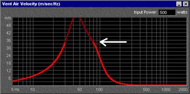
In the graph above the plot line color changes to a darker shade when it rises above 34 m/s (112 ft/s) to warn that the vent may produce unwanted noise at the specified frequencies and with the specified input power (500 watts in this example).
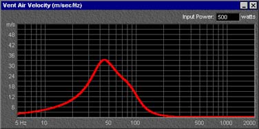
Ideally, the vent air velocity should stay below 34 m/s at all frequencies at the maximum input power level as shown in the graph below.
If the input power and driver are not changed, there is only one way to decrease the vent air velocity: increase the total vent cross-section area. This can be accomplished by simply increasing the diameter of the vent or by increasing the number of vents. For example, you could use two vents instead of one. However there is a potential disadvantage: increasing the vent cross-section area or number of vents requires the vent(s) to be longer. Another technique is to use a vent with a flare at each end to reduce the vent turbulence at the mouth of the vent. However, even a vent with flared ends will create unwanted noise if it is too small.
For convenience, the "Vents" tab of the "Box Properties" window includes a "Suggest Minimum Vent Area for Xmax" button (shown below) which will calculate a vent diameter that should prevent vent noise when the driver is driven with the full rated power specified by the driver parameter "Pe" and at the maximum linear one-way excursion specified by "Xmax".
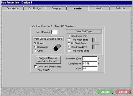
Note: BassBox Lite has the same feature on the "Vent" tab of its "Design Properties" window.
Fit
The vent must be small enough to fit the box. It should be mounted away from all walls or structures that may affect the movement of air in and out of the vent. Generally this means keeping each end of the vent at least one vent diameter away from side or back walls, braces and stuffing or fill.
Usually the dimension that causes the problem is the vent length. When a vent is too long to fit inside a box it may indicate that the box is being tuned to too low of a frequency. Note: When BassBox Pro thinks that a vent is too long, it will turn the vent length (Lv) value red and add a red warning message to the "Dimensions" frame of the "Box Design" tab. BassBox Lite does the same thing with Lv on its "Vent" tab and the "Dimensions" frame on its "Box" tab, both in its "Design Properties" window.
There are several ways to reduce the vent length: you could raise the system resonance frequency (Fb), increase the box or chamber internal volume (Vb), decrease the vent diameter or cross-section area or decrease the number of vents. Of course, if the vent is made too small then you may have a problem with vent turbulence as discussed in the first point above.
Resonance
When most designers think of "vent resonance" they usually think instead of "Fb", the system resonance that results from the combination of the box or chamber internal volume and the vent dimensions. It is also referred to as the system "tuning frequency".
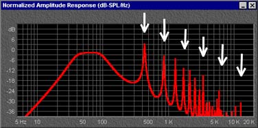
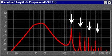
However, the system resonance (Fb) is not the same as the "vent resonance". Every vent has its own resonance and associated harmonics that are dependent only on the vent dimensions and this is what we refer to when we say "vent resonance". This vent-only resonance is also referred to as the "pipe resonance" and it can have a dramatic effect on bandpass box designs as shown below and highlighted with the white arrows.
In order to see these vent resonance peaks in the BassBox Pro/Lite amplitude response graphs you need to turn on the "Include > Vent Resonance Peaks" option. In BassBox Pro, this is done with either the the graph pop-up menu or the "Graph Properties" palette. In BassBox Lite, this is done in its "Graph" menu. Of course, the vent dimensions must also be entered.
Vent resonance is usually not a problem for standard vented boxes for several reasons. The drivers function as direct radiators and the system acts as a high-pass filter allowing the upper frequency response of the driver to mask the resonance peaks of a vent. However, bandpass boxes produce all of their sound through vents and the upper frequency roll-off of bandpass systems can expose their larger vent resonance peaks.
These vent resonance peaks do not always sound as bad as they look. They are sometimes very narrow and therefore difficult to hear or measure. However, when they rise high enough and have sufficient width (and therefore energy) they can be very audible.
How can unwanted vent resonance peaks be minimized? The resonance frequency of smaller vents are higher in frequency and therefore present less of a problem because of the high-frequency roll-off of a bandpass box. Reducing the vent diameter or cross-section area or reducing the number of vents in the affected chamber will push the resonance peaks to higher frequencies as shown below:
The bandpass box above has a vent diameter that is about 30% smaller than the example before it. This causes the resonance peaks to shift upward approximately one octave. However, if the vent is made too small then you may have a problem with vent turbulence as discussed at the beginning of this topic.
There is another way to minimize the effects of the vent resonance peaks: add a low-pass filter to the design. Either a passive or active low-pass filter can be used.
Summary
Successful vent design often requires skillful balancing of the vent dimensions so that the vent is big enough to avoid vent turbulence noise, small enough to fit in the box and, if the box is a bandpass design, small enough to avoid vent resonance peak problems. There may be times when a vent simply won't work. After all, you can't bend the laws of physics and small boxes or chambers cannot be tuned to low frequencies without large vents no matter what driver is used. If a desired vent just won't fit in the box, then you should consider changing the design. You could use a different driver and a larger box. Or you could switch to a different box design. For example, a passive radiator can achieve a similar response as a vent. You could also switch to a closed box design but this will move the cut-off frequency higher. This latter problem can be overcome with active equalization as long as the driver can handle the added excursion but BassBox 6 Pro/Lite do not model active equalizers so you will need to experiment to find the best settings. Making these decisions is the "art" in loudspeaker design.